Last summer, our team was called out to diagnose a persistent air conditioning compressor failure in a client's RV — the third replacement in two seasons. The culprit was not the compressor itself but chronically low campground voltage hovering around 105V. That experience reinforced what we have long advised: understanding how autoformers work is essential for anyone relying on shore power in environments where voltage sags are routine. An autoformer is a single-winding transformer that boosts or regulates incoming AC voltage without isolating the circuit, and its simplicity is precisely what makes it so effective. For those already familiar with automotive electrical systems, the underlying principles translate directly.
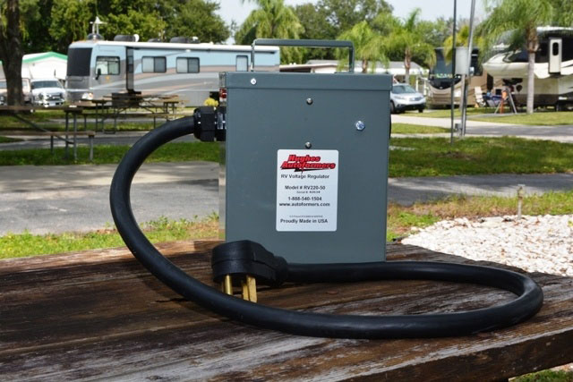
Unlike isolation transformers, which use separate primary and secondary windings, an autoformer shares a single copper winding with multiple taps. This design results in a smaller, lighter, and more efficient unit — critical factors when space and weight matter, as they do in recreational vehicles and mobile workshops. The trade-off is that the autoformer does not provide galvanic isolation, meaning the input and output share a common ground path. For most voltage-correction applications, that trade-off is well worth it.
The technology is not new. Autoformers have been used in industrial power conditioning for decades, and the operating principles are identical whether the unit sits in a factory or at a campsite. What has changed is accessibility — modern consumer-grade autoformers from manufacturers like Hughes and Progressive Industries have made this technology practical for everyday use, and understanding the mechanics behind them separates informed maintenance from guesswork.
Contents
- How Autoformers Work: Core Operating Principles
- Essential Tools and Equipment for Autoformer Installation
- Diagnosing Autoformer Issues: A Troubleshooting Guide
- Autoformer Myths That Refuse to Die
- Advantages and Drawbacks of Autoformer Systems
- When an Autoformer Makes Sense — and When It Does Not
- Common Autoformer Mistakes and How to Avoid Them
- Frequently Asked Questions
- Key Takeaways
How Autoformers Work: Core Operating Principles
At the most fundamental level, an autoformer operates on the same electromagnetic induction principles as any transformer. A single continuous copper winding is wrapped around a laminated steel or toroidal core, and different taps along this winding allow the device to output a voltage higher (or lower) than the input. Because the input and output circuits share the winding, the autoformer transfers energy both conductively and inductively — resulting in efficiency ratings typically above 95%.
Tap-Switching Mechanism
Modern consumer autoformers use relay-driven tap switching to select the appropriate boost level automatically. The internal control board continuously monitors incoming voltage and engages the correct tap when voltage falls below a preset threshold. Most units operate on a tiered system:
- Input above 120V — no boost applied (bypass mode)
- Input between 108V and 120V — minor boost engaged (typically 8–10%)
- Input between 104V and 108V — full boost engaged (typically 10–12%)
- Input below 104V — unit disconnects power entirely to protect connected equipment
The tap switching is not instantaneous. There is a brief relay transition period — usually under 100 milliseconds — during which output momentarily drops. For resistive loads like heaters, this is inconsequential. For sensitive electronics, a downstream UPS or line conditioner may be warranted.
Pro Insight: The relay click heard during tap changes is normal operation, not a fault. Frequent clicking indicates the incoming voltage is oscillating right at a tap threshold — a sign of unstable supply rather than autoformer malfunction.
Voltage Boost Ratios and Winding Design
The boost ratio is fixed by the physical winding tap positions. An autoformer cannot produce arbitrary voltage — it steps up by the ratio determined at manufacturing. This is fundamentally different from electronic voltage regulators, which use solid-state circuitry to produce continuously variable output. The fixed-ratio design is both the autoformer's greatest strength (simplicity, reliability, no active components to fail) and its primary constraint (limited to discrete boost steps).

The winding wire gauge directly determines the unit's current capacity. A 30-amp autoformer uses heavier gauge wire than a 15-amp model, and this is why amperage ratings must never be exceeded — the wire will overheat, potentially damaging the insulation and creating a fire hazard. Anyone familiar with the principles behind wiring a light bar on a Jeep already understands how wire gauge, amperage, and heat dissipation interact.
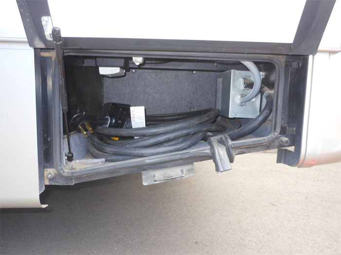
Essential Tools and Equipment for Autoformer Installation
A proper autoformer installation requires more than plugging in a cord. Our team has standardized on a specific set of tools and equipment that ensures safe, code-compliant installations every time.
Wiring and Circuit Requirements
- Dedicated circuit — the autoformer must be the first device in the power chain, ahead of surge protectors or EMS units
- Appropriately rated inlet/outlet receptacles (NEMA TT-30 for 30A, NEMA 14-50 for 50A)
- Copper conductors sized per NEC Table 310.16 — never aluminum for portable installations
- Proper grounding conductor bonded to the frame or ground bus
- Weather-resistant enclosure if installed in exposed locations
Monitoring Instruments
An autoformer without monitoring is operating blind. At minimum, the installation should include:
| Instrument | Purpose | Recommended Accuracy | Placement |
|---|---|---|---|
| True-RMS Multimeter | Verify input/output voltage | ±0.5% | Handheld — pre/post installation checks |
| Inline Voltage Monitor | Continuous voltage display | ±1V | Between autoformer output and load panel |
| Clamp Ammeter | Measure current draw | ±2% | Handheld — periodic load verification |
| Kill-A-Watt or Equivalent | Per-appliance power audit | ±0.5% | Individual outlet monitoring |
| Infrared Thermometer | Detect hot connections | ±2°F | Handheld — connection point surveys |
The infrared thermometer is often overlooked but is critical. Loose or corroded connections generate heat long before they fail, and a thermal scan of all connection points after 30 minutes under load will reveal problems invisible to the eye. This same diagnostic principle applies broadly across automotive electrical work.
Diagnosing Autoformer Issues: A Troubleshooting Guide
Most autoformer problems trace back to three root causes: inadequate input power, connection failures, or exceeding the unit's rated capacity. The diagnostic process should be systematic.
No Voltage Boost Detected
When the output voltage matches the input with no boost applied, the autoformer is likely in bypass mode — meaning input voltage is above the boost threshold. This is correct behavior. Before assuming a fault:
- Measure input voltage at the pedestal, not at the autoformer's input terminals — voltage drop across a long or undersized extension cord can be significant
- Verify the autoformer's indicator LEDs or display correspond to the measured input
- Check that the unit is not in a post-fault lockout state requiring a manual reset
If input voltage is genuinely low (below the boost threshold) and no boost engages, the internal relays or control board may have failed. Relay failure is the most common wear-related fault in units with high tap-switching cycles.
Intermittent Output Fluctuations
Intermittent voltage fluctuations on the output side typically indicate one of two conditions. The first is input voltage oscillating near a tap threshold, causing repeated relay switching. The solution is to identify and address the unstable supply — overloaded campground transformer, undersized feeder wiring, or time-of-day demand spikes. The second is corroded or pitted relay contacts, which create momentary open-circuit conditions during switching. Relay contact resistance increases over time, particularly in humid or salt-air environments.
Warning: Never bypass autoformer relay contacts with jumper wires to "test" the winding. This eliminates the low-voltage disconnect protection and can feed dangerously high voltage to connected equipment if the supply recovers.
Autoformer Myths That Refuse to Die
Misinformation about autoformers persists across forums and social media. Our team encounters the same misconceptions repeatedly, and they lead to both unnecessary purchases and dangerous misapplications.
The Surge Protector Confusion
An autoformer is not a surge protector. This distinction is critical. An autoformer corrects sustained low voltage — a chronic condition. A surge protector clamps transient high-voltage spikes — an acute event measured in microseconds. Some manufacturers combine both functions into a single unit (Hughes markets models with built-in surge protection), but the two functions are independent. Owning an autoformer does not protect against lightning-induced surges, and a surge protector does nothing for chronic low voltage.
The U.S. Department of Energy provides comprehensive documentation on power distribution challenges that contextualize why both types of protection serve distinct purposes.
The "Free Power" Misconception
A persistent myth suggests that autoformers "create" additional power. They do not. An autoformer boosts voltage by drawing proportionally more current from the supply. If an autoformer boosts 110V to 122V — a roughly 11% increase — the input current increases by approximately 11% to compensate. Power in equals power out, minus small losses in the winding and core. There is no thermodynamic loophole.
This matters practically because the increased input current can trip a pedestal breaker that was already near capacity. A 30-amp pedestal circuit feeding a 30-amp autoformer at full boost is effectively being asked to deliver 33+ amps on the input side. Awareness of this current multiplication effect separates competent installations from hazardous ones.
Advantages and Drawbacks of Autoformer Systems
No power conditioning solution is universally superior. The autoformer occupies a specific niche, and understanding its boundaries prevents both over-reliance and unnecessary dismissal.
Where the Autoformer Excels
- Passive reliability — no active electronic components in the power path means fewer failure modes than inverter-based solutions
- High efficiency (95%+) translates to minimal heat generation and wasted energy
- No waveform distortion — the output is a clean sinusoidal waveform identical to the input, just at higher voltage
- Long service life — quality units last 15–20 years with minimal maintenance
- No battery requirement — unlike UPS systems, autoformers operate continuously without stored energy
Known Limitations
- Cannot correct high voltage — only boosts low voltage (some models include high-voltage disconnect, but they do not reduce voltage)
- Fixed boost ratios mean the output voltage tracks with input variations, just offset higher
- No galvanic isolation — ground faults and neutral-ground bonds on the supply propagate through
- Current multiplication on the input side can overload supply circuits at full boost
- Physical size and weight scale with amperage rating — 50-amp units are substantial
The efficiency advantage deserves emphasis. Electronic voltage regulators achieve similar correction but often introduce harmonic distortion and generate considerable heat under load. For motor-driven appliances like compressors and fans — which are sensitive to waveform quality — the autoformer's clean output is a meaningful advantage. This parallels how synthetic oil advantages manifest differently depending on the specific engine and operating conditions — context determines whether a particular technology is the right fit.
When an Autoformer Makes Sense — and When It Does Not
Deploying an autoformer is a targeted solution to a specific problem. It is not a universal power conditioner, and misapplication wastes money at best and creates hazards at worst.
Ideal Deployment Scenarios
An autoformer is the correct choice when:
- Shore power voltage consistently reads below 115V but above 104V — the "sag zone" where appliances strain but power remains usable
- Air conditioning compressors are cycling on thermal overload due to low voltage — this is the single most common trigger for autoformer purchases
- The installation location has no access to alternative power infrastructure (generator, inverter, electrical service upgrade)
- Load requirements are well within the autoformer's amperage rating, with at least 20% headroom
RV parks and older residential circuits with long feeder runs are the classic deployment environments. In these settings, the autoformer addresses the root cause (insufficient voltage) rather than treating symptoms.
Poor-Fit Situations
An autoformer is the wrong tool when:
- Voltage drops below 104V regularly — this indicates a supply problem severe enough that boosting is unsafe. The supply wiring or transformer needs attention
- The primary concern is surge or spike protection — a dedicated surge protector or EMS is required
- Sensitive electronic equipment demands regulated, isolated power — a true isolation transformer or online UPS is appropriate
- The supply circuit is already loaded near capacity — the input current multiplication will trip breakers
Tip: Before purchasing an autoformer, log the supply voltage over a full 24-hour period using an inexpensive data-logging multimeter. Voltage sags that only occur during peak demand hours (typically 14:00–20:00) may indicate a shared transformer problem that the park or utility should address at no cost to the end user.
Common Autoformer Mistakes and How to Avoid Them
Our team has documented a recurring set of errors across hundreds of installations and service calls. Most are entirely preventable with basic awareness of how autoformers work and their inherent constraints.
Installation Errors
Placing the autoformer downstream of a surge protector or EMS. The autoformer must be the first device connected to shore power. A surge protector between the pedestal and autoformer sees the low input voltage and may disconnect power unnecessarily, or its internal resistance creates additional voltage drop before the autoformer can compensate. The correct order is always: pedestal → autoformer → surge protector/EMS → load panel.
Using undersized extension cords. A 50-foot 10-gauge extension cord between the pedestal and autoformer introduces 3–5V of additional drop at 30 amps. This can push the input voltage below the autoformer's operating floor, triggering a disconnect. Use the shortest cord possible, and never less than 10 AWG for 30-amp service or 6 AWG for 50-amp service. The same wire-sizing discipline that applies to wiring auxiliary lighting applies here — undersized conductors create heat and voltage loss.
Ignoring grounding requirements. The autoformer's chassis must be properly grounded. Because there is no galvanic isolation, a ground fault on the supply side will propagate through the autoformer. Without proper grounding, fault current has no safe return path, and GFCI protection downstream may not trip.
Operational Oversights
Running at or near rated capacity continuously. A 30-amp autoformer can handle 30 amps, but sustained operation above 80% of rated capacity accelerates thermal aging of the winding insulation. Our team recommends treating the rated amperage as a ceiling, not a target.
Neglecting periodic connection inspections. Plug and receptacle connections are the weak link in any portable power chain. Oxidation, heat cycling, and mechanical wear degrade connections over time. An annual inspection — cleaning contacts, checking for discoloration or deformation, verifying torque on terminal screws — extends the life of both the autoformer and connected equipment significantly.
Failing to account for inrush current. Motor-driven compressors draw 3–5 times their running current during startup. This inrush, multiplied by the autoformer's boost ratio, can momentarily exceed the input circuit's capacity. Staggering startup of large loads — running the air conditioner for 30 seconds before starting the refrigerator — reduces peak inrush demand on both the autoformer and supply circuit.
Frequently Asked Questions
Does an autoformer protect against power surges?
No. An autoformer corrects sustained low voltage only. It does not clamp transient voltage spikes. Surge protection requires a dedicated surge protector or electronic management system (EMS) installed downstream of the autoformer. Some combination units integrate both functions, but the autoformer winding itself provides no surge suppression capability.
Can an autoformer damage appliances by delivering too much voltage?
It is possible if the input voltage is already at or above nominal. An autoformer that boosts a 124V input by 10% would output approximately 136V — well above the safe operating range for most household appliances. Quality units include a high-voltage bypass or disconnect feature that prevents boosting when input voltage is already adequate, but verifying this feature exists in a specific model before purchase is essential.
What is the difference between an autoformer and a voltage regulator?
An autoformer uses a single-winding transformer with fixed tap ratios to boost voltage in discrete steps. A voltage regulator (electronic type) uses solid-state circuitry to deliver a continuously variable, precisely regulated output voltage. The autoformer is simpler, more efficient, and produces a cleaner waveform, but cannot fine-tune output to an exact target. Electronic regulators offer tighter regulation but introduce harmonic distortion and generate more heat.
How long does a typical autoformer last?
A quality autoformer from established manufacturers lasts 15–20 years under normal operating conditions. The winding and core are passive components with no inherent wear mechanism. The primary failure points are the tap-switching relays (rated for 50,000–100,000 cycles) and the control board electronics. Units operated in humid, salt-air, or dusty environments will see accelerated relay and connector degradation, making periodic inspection and contact cleaning essential for longevity.
Key Takeaways
- An autoformer boosts low AC voltage using a single shared winding with fixed tap ratios, delivering 95%+ efficiency and a clean sinusoidal output — but it does not provide surge protection or galvanic isolation.
- Proper installation sequence (pedestal → autoformer → surge protector → load panel), appropriate wire gauge, and solid grounding are non-negotiable for safe operation.
- The input current multiplication effect means a fully boosted autoformer draws more amperage from the supply than it delivers to the load — always verify the supply circuit has headroom before deploying.
- A 24-hour voltage log before purchase prevents wasted investment; if supply voltage regularly drops below 104V, the supply infrastructure itself needs repair rather than downstream compensation.


About Chris Lewis
Chris Lewis developed a deep knowledge of automotive filtration, maintenance, and repair through years of hands-on experience working on vehicles — a passion rooted in time spent in his father's San Francisco auto shop from an early age. He has practical familiarity with air, oil, fuel, and cabin filter systems across a wide range of vehicle makes and models, along with experience evaluating the tools and equipment that serious DIY mechanics rely on. At MicrogreenFilter, he covers automotive and motorcycle filter reviews, maintenance guides, and automotive tool recommendations.
Get FREE Filters now. Or latest free tools from our best collections.
Disable Ad block to get all the secrets. Once done, hit any button below